Tutorial(First Steps): Difference between revisions
m →A beginner's walk-through to XDS: update |
|||
| (9 intermediate revisions by the same user not shown) | |||
| Line 3: | Line 3: | ||
This tutorial is directed at people who are beginners to XDS and do not want to start reading about all the technical details but rather want their images processed. Other processing programs are often more attractive to new users because using a GUI make starting easier than a [[XDS.INP|script file]]. If you notice a mistake or gap in this tutorial, please contact the authors. | This tutorial is directed at people who are beginners to XDS and do not want to start reading about all the technical details but rather want their images processed. Other processing programs are often more attractive to new users because using a GUI make starting easier than a [[XDS.INP|script file]]. If you notice a mistake or gap in this tutorial, please contact the authors. | ||
In the following, the manual mode of setting up XDS.INP is explained. | In the following, the manual mode of setting up [[XDS.INP]] and running XDS is explained. | ||
There is also a [[generate_XDS.INP|script]] that sets up XDS.INP automatically, at least for common types of detectors. Much easier than setting up and running XDS manually should be the usage of [[XDSGUI]]. | |||
== Setting up == | == Setting up == | ||
| Line 9: | Line 11: | ||
It is not recommended to process the images from within the same directory as the images are. At least create a subdirectory. In many cases the data images are on an external disk or remotely mounted directory with an awfully long path name. | It is not recommended to process the images from within the same directory as the images are. At least create a subdirectory. In many cases the data images are on an external disk or remotely mounted directory with an awfully long path name. | ||
If | If your images are at a path with embedded blanks, e.g. "/my/USB disk/path", XDS is not able to access the images and one must create a link to the actual directory: | ||
#> ln -s "/my/USB disk/path" images | |||
=== Getting [[XDS.INP]] === | === Getting [[XDS.INP]] === | ||
You must know the type of detector your data were collected on. Then visit the [http:// | You must know the type of detector your data were collected on. Then visit the [http://xds.mpimf-heidelberg.mpg.de/html_doc/xds_prepare.html XDS Homepage], download the appropriate template and rename it to [[XDS.INP]]. | ||
== Editing [[XDS.INP]] == | == Editing [[XDS.INP]] == | ||
This tutorial uses the template for XDS-MARCCD.INP (templates can be downloaded from [http:// | This tutorial uses the template for XDS-MARCCD.INP (templates can be downloaded from [http://xds.mpimf-heidelberg.mpg.de/html_doc/xds_prepare.html]. | ||
Open [[XDS.INP]] with your favourite text editor (e.g. gedit, kate, kwrite, vim, emacs...) and make the following adjustments (from top to bottom): | Open [[XDS.INP]] with your favourite text editor (e.g. gedit, kate, kwrite, vim, emacs...) and make the following adjustments (from top to bottom): | ||
* '''Pixel Size''' Find out the number of pixels of your detector. A very good program to find this is [http://www.scripps.edu/~arvai/adxv.html adxv] (also see the wiki article [[adxv]]): It allows to view the '''image header''' where these numbers often can be found. [[Image:Adxv_menu.jpeg|200px|adxv image viewer, main menu]] [[Image:Adxv_pixelsize.jpeg|300px|adxv showing image header info. Pixel size is highlighted]] | |||
* '''Adjusting JOB Card''' Make a copy of the '''JOB''' line in [[XDS.INP]] for reference. Comment out one line by putting a exclamation mark "!" at the beginning of the line and prepare the other one to run the steps from XYCORR to CORRECT.[[Image:XDS_INP_adjustingJOB.jpeg|400px|Adjusting the JOB card in XDS.INP]] | |||
* '''ORGX and ORGY''' Unless you can guess the direct beam position on the images, ''e.g.'' from ice rings, set both these values to half the detector size. In the case of this example, where the MAR-CCD is 3072x3072 pixels, this means | |||
ORGX=1536.00 ORGY=1536.00 !Detector origin (pixels). | ORGX=1536.00 ORGY=1536.00 !Detector origin (pixels). | ||
* '''Experiment specific settings''' The following numbers are also usually found in the image header (or in your lab notebook, or in logs written by the beamline software): | |||
DETECTOR_DISTANCE= 150.0 !(mm) | DETECTOR_DISTANCE= 150.0 !(mm) | ||
OSCILLATION_RANGE=1.0 !degrees (>0) | OSCILLATION_RANGE=1.0 !degrees (>0) | ||
X-RAY_WAVELENGTH=1.07176 !Angstroem | X-RAY_WAVELENGTH=1.07176 !Angstroem | ||
NAME_TEMPLATE_OF_DATA_FRAMES=./images/tutorial_????.img ! TIFF | NAME_TEMPLATE_OF_DATA_FRAMES=./images/tutorial_????.img ! TIFF | ||
DATA_RANGE=1 | DATA_RANGE=1 180 !Numbers of first and last data image collected | ||
SPOT_RANGE=1 90 !images to be used for indexing; 1 180 would be better unless there is radiation damage | |||
Then data processing can start. type <pre>#> xds_par </pre> to run xds and wait until it's finished. | |||
== Indexing Fails == | == Indexing Fails == | ||
| Line 39: | Line 41: | ||
!!! ERROR !!! SOLUTION IS INACCURATE | !!! ERROR !!! SOLUTION IS INACCURATE | ||
Do the following: | Do the following: | ||
* In IDXREF.LP, find the table '''INDEXING OF OBSERVED SPOTS IN SPACE GROUP''' | |||
***** INDEXING OF OBSERVED SPOTS IN SPACE GROUP # 1 ***** | ***** INDEXING OF OBSERVED SPOTS IN SPACE GROUP # 1 ***** | ||
16196 OUT OF 76452 SPOTS INDEXED. | 16196 OUT OF 76452 SPOTS INDEXED. | ||
| Line 49: | Line 51: | ||
DETECTOR ORIGIN (PIXELS) AT 1514.16 1537.27 | DETECTOR ORIGIN (PIXELS) AT 1514.16 1537.27 | ||
as improved ORGX and ORGY to [[XDS.INP]] and try indexing again. | as improved ORGX and ORGY to [[XDS.INP]] and try indexing again. | ||
XDS is quite robust and in many cases this approach works | XDS is quite robust and in many cases this approach works. If not, read [[Obtaining ORGX ORGY]]. | ||
* Check the refined detector distance | |||
DETECTOR ORIGIN (PIXELS) AT 1514.16 1537.27 | DETECTOR ORIGIN (PIXELS) AT 1514.16 1537.27 | ||
CRYSTAL TO DETECTOR DISTANCE (mm) 422.92 | CRYSTAL TO DETECTOR DISTANCE (mm) 422.92 | ||
If it deviates by more than 1-2mm from the input distance, check all | If it deviates by more than 1-2mm from the input distance, check all your parameters again. Is the wavelength really correct, as well as the distance? If you are sure about them, try indexing with only a few images | ||
SPOT_RANGE = 1 20 | SPOT_RANGE = 1 20 | ||
== See also == | |||
[https://{{SERVERNAME}}/pub/MWhitley_CSHL-2018_XDS-Tutorial.pdf Matthew J. Whitley's excellent tutorial] about XDS processing with [[XDSGUI]], from the 2018 Cold Spring Harbor X-Ray Methods in Structural Biology Course. | |||
Latest revision as of 15:46, 15 July 2023
A beginner's walk-through to XDS
This tutorial is directed at people who are beginners to XDS and do not want to start reading about all the technical details but rather want their images processed. Other processing programs are often more attractive to new users because using a GUI make starting easier than a script file. If you notice a mistake or gap in this tutorial, please contact the authors.
In the following, the manual mode of setting up XDS.INP and running XDS is explained.
There is also a script that sets up XDS.INP automatically, at least for common types of detectors. Much easier than setting up and running XDS manually should be the usage of XDSGUI.
Setting up
Image Location
It is not recommended to process the images from within the same directory as the images are. At least create a subdirectory. In many cases the data images are on an external disk or remotely mounted directory with an awfully long path name. If your images are at a path with embedded blanks, e.g. "/my/USB disk/path", XDS is not able to access the images and one must create a link to the actual directory:
#> ln -s "/my/USB disk/path" images
Getting XDS.INP
You must know the type of detector your data were collected on. Then visit the XDS Homepage, download the appropriate template and rename it to XDS.INP.
Editing XDS.INP
This tutorial uses the template for XDS-MARCCD.INP (templates can be downloaded from [1].
Open XDS.INP with your favourite text editor (e.g. gedit, kate, kwrite, vim, emacs...) and make the following adjustments (from top to bottom):
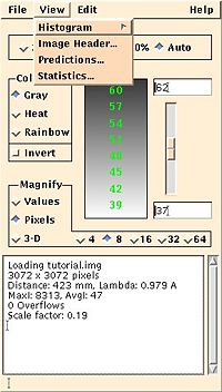
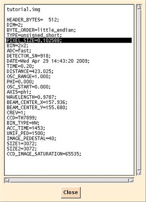
- Pixel Size Find out the number of pixels of your detector. A very good program to find this is adxv (also see the wiki article adxv): It allows to view the image header where these numbers often can be found.


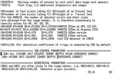
- Adjusting JOB Card Make a copy of the JOB line in XDS.INP for reference. Comment out one line by putting a exclamation mark "!" at the beginning of the line and prepare the other one to run the steps from XYCORR to CORRECT.

- ORGX and ORGY Unless you can guess the direct beam position on the images, e.g. from ice rings, set both these values to half the detector size. In the case of this example, where the MAR-CCD is 3072x3072 pixels, this means
ORGX=1536.00 ORGY=1536.00 !Detector origin (pixels).
- Experiment specific settings The following numbers are also usually found in the image header (or in your lab notebook, or in logs written by the beamline software):
DETECTOR_DISTANCE= 150.0   !(mm)
OSCILLATION_RANGE=1.0            !degrees (>0)
X-RAY_WAVELENGTH=1.07176         !Angstroem
NAME_TEMPLATE_OF_DATA_FRAMES=./images/tutorial_????.img  ! TIFF
DATA_RANGE=1 180    !Numbers of first and last data image collected
SPOT_RANGE=1  90    !images to be used for indexing; 1 180 would be better unless there is radiation damage
Then data processing can start. type
#> xds_par
to run xds and wait until it's finished.
Indexing Fails
If the detector origin is too far from the image centre, IDXREF is going to stop with the error message
!!! ERROR !!! SOLUTION IS INACCURATE
Do the following:
- In IDXREF.LP, find the table INDEXING OF OBSERVED SPOTS IN SPACE GROUP
***** INDEXING OF OBSERVED SPOTS IN SPACE GROUP #   1 *****
  16196 OUT OF   76452 SPOTS INDEXED.
      0 REJECTED REFLECTIONS (REASON: OVERLAP)
  60256 REJECTED REFLECTIONS (REASON: TOO FAR FROM IDEAL POSITION)
EXPECTED ERROR IN SPINDLE  POSITION     2.398 DEGREES
EXPECTED ERROR IN DETECTOR POSITION      1.72 PIXELS
Unless really hardly any reflections could be indexed (second line in the table), scroll a few lines up and copy the refined values for the beam origin
DETECTOR ORIGIN (PIXELS) AT 1514.16 1537.27
as improved ORGX and ORGY to XDS.INP and try indexing again. XDS is quite robust and in many cases this approach works. If not, read Obtaining ORGX ORGY.
- Check the refined detector distance
DETECTOR ORIGIN (PIXELS) AT                     1514.16   1537.27
CRYSTAL TO DETECTOR DISTANCE (mm)       422.92
If it deviates by more than 1-2mm from the input distance, check all your parameters again. Is the wavelength really correct, as well as the distance? If you are sure about them, try indexing with only a few images
SPOT_RANGE = 1 20
See also
Matthew J. Whitley's excellent tutorial about XDS processing with XDSGUI, from the 2018 Cold Spring Harbor X-Ray Methods in Structural Biology Course.